Pressure switch technology has numerous practical applications, but in order to ensure the optimal functionality of these adjustable devices, calibrating them correctly is of chief importance. First and foremost, don’t start fiddling with the settings of pressure switches before you understand the fundamental terminology and concepts. Let’s take a look at what they entail.
Setpoints
Setpoints constitute the pressure levels that determine the switch to activate. There are two types of settings in this sense, namely:
• Low level alarms: the switch will trigger whenever the pressure on it decreases;
• High level alarms: the switch will trigger whenever the pressure on it increases;
Almost all pressure switches function in accordance with predefined pressure points, which means that these settings are relative to the local atmospheric pressure values. In a limited number of applications, the setpoint is adjusted to absolute zero, meaning that atmospheric pressure is considered to be null. For most situations, the most feasible setpoint value ranges between 25 percent and 75 percent.
Deadband
The deadband, in this context, represents the value or percentage of the variation required to reset the pressure switch to the default condition after it has triggered. Also referred to as switching differentials or reset readings, deadbands are defined as the variation between increasing and decreasing pressure on the switch. Fixed differential designs require deadbands between 1 percent and 3 percent, whereas adjustable differential designs operate on deadbands intervals between 5 percent and 12 percent.
Before the calibration
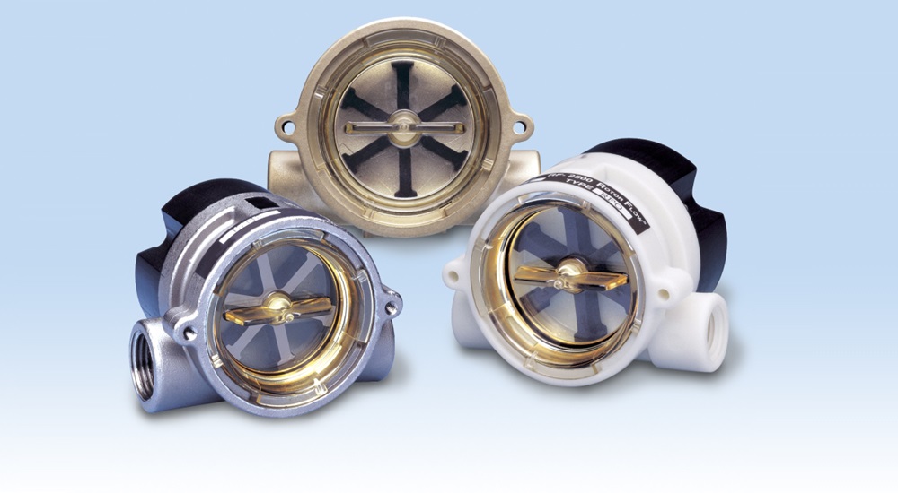
It’s necessary to remember that there are various types of pressure switches available, and selecting the appropriate one for your application should be the first step of the process. For example, a vacuum switch won’t perform optimally in an environment that necessitates a hydraulic or differential design version.
At the same time, before commencing the calibration, the setpoints and deadband values must be confirmed. Don’t start working on the switches before they have been depressurized and/or electrically isolated, especially in situations when exposure to high voltage electrical currents is necessary for accessing the pressure switch. Once you have followed these recommendations, here’s what you need to do.
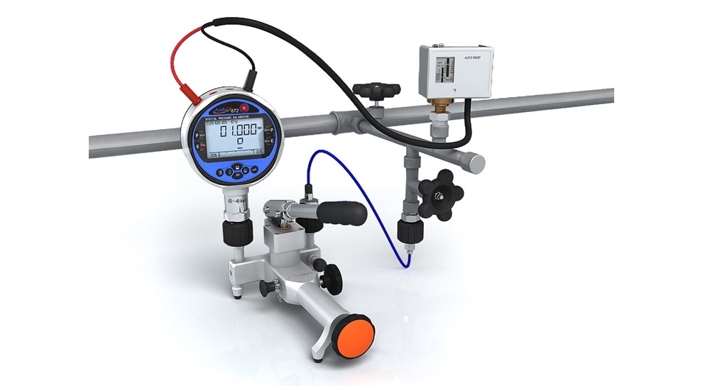
1. Connecting the pressure switch
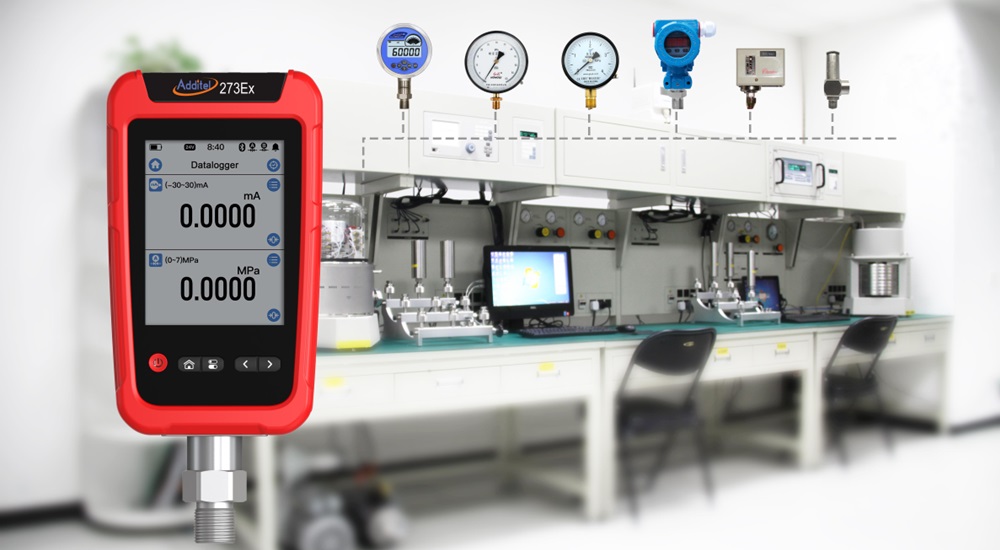
To be able to check the parameters, you’ll first have to power the unit and then proceed to testing the gauge. The generally recommended utensils for this purpose are hand regulators, but specific applications may require other power sources; check the instruction manual for more details.
2. Checking the settings of the contacts
Utilizing either ohmmeters or digital multimeters adjusted in the continuity intervals, verify if the settings of the pressure switch’s contacts are correct. Normally Closed or NC and Normally Open or NO comprise the options.
3. Verify the increasing pressure setpoint
After connecting the terminal to the NO, read the power source’s data and ensure that it indicates an open circuit. Increasing the setpoint until a changeover in the contacts occurs and the meter shows a circuit that will give you the increasing pressure setpoint.
4. Verify the decreasing pressure setpoint
With the setpoint in the peak rating, start gradually decreasing the level from NC to NO. The data on the display should be the decreasing pressure setpoint.
5. Calculate the deadband
Subtract the values of the two aforementioned readings and you’ll obtain the pressure switch’s deadband. All you have to do now is contrast the readings against the manufacturer specs, and its value should be lower or of almost equal value to them.